
The remote was opened by removing the screws in the back using the special triangle-tip screwdriver bits available at Greg Wilson's Office in the Clyde. Any computer or exotic tool supply place should carry such bits. Inside, we found the internals intact, no obvious damage. Now to discover exactly why this was labeled "dead". The battery terminals are marked with the appropriate + and - symbols, and so assuming 3.0 volts from two 1.5 volt batteries, we applied power using a lab power supply. The first thing noticed was that the current draw was high, almost 1.2 amps. The BroadCom chip in the rough lower third-center of the board immediately started getting hot, putting out around 3 watts of heat! This is good news, really, because this means that the main power system is supplying everything to a short in the BroadCom, probably in the ball-grid-array soldering on the underside, so the chances of electrical damage on the other parts on the board is low because they could not possibly have received any kind of damaging voltage, in other words, everything else should be preserved. Measuring on the camera's pins, we verified that the voltage to it's supplies were barely over 1 volt, and ground was at the same level as the power supply ground.

To desolder the camera, we used a plunger-style solder sucker, but quickly moved to the solder wick. The solder on the 8 pins was removed as much as possible, even to the point that they broke free of the holes they were inserted into. This is critical, actually, as attempts to free another Wii Remote's camera ended in tragedy when the pins were ripped out during this final step: Once the pins are desoldered, attack the two side tabs that are rigorously inserted into the mounting holes on the board. The use of a vice grip was necessary while twisting and pulling under heat.

With the camera extracted, 6 of the 8 pins were soldered to breadboard wire, observing this guy's pin diagram:

The breadboard wire leads were attached to a 1 by 6 .1 inch-spaced male header pin strip, in this order:
3.3v, GND, SCL, SDA, CLK, RST
This somewhat maintains the original pattern and allows straight-out wires, no overlap.
More Information, email style:
Below is an email that I had sent to Raymond in our process of getting this put together.

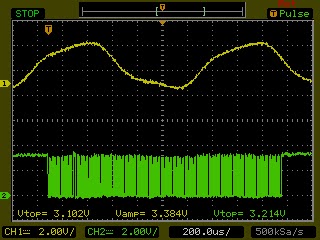


Video of the camera being tested on the Wii-BlobTrack software program referenced at http://letsmakerobots.com/node/7752 .
Wii Remote Vision System Hacked from Stephen Carlson on Vimeo.